Scara solution: From the idea to the product Episode 3
Marius Glaue | 13. August 2020
Clarification on episode 2
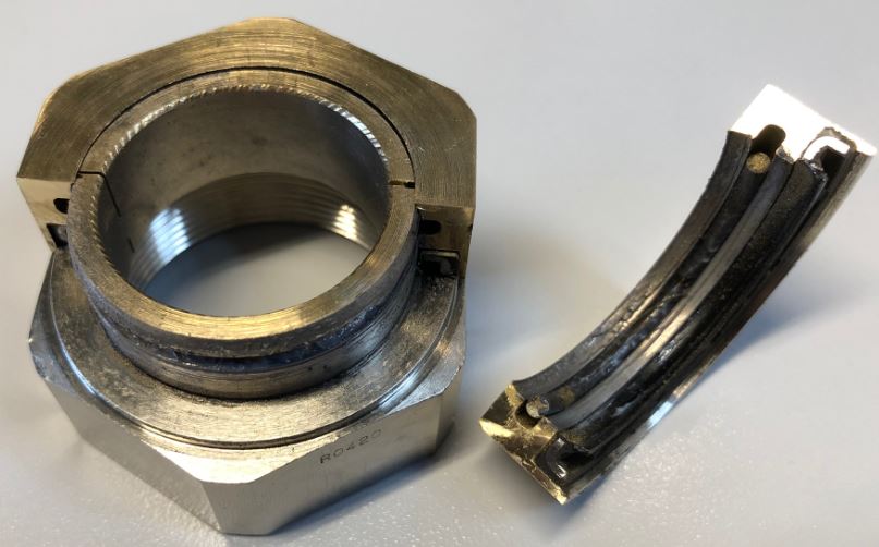
Before I start with the 3rd episode of the Scara solution, I would like to clear up the last picture of episode 2. The picture shows the cut open and dismantled metal rotary connection bearing. To get an idea of the inner workings, we cut open the part without further ado and looked at how it is constructed. We decided to take this step because we were not completely satisfied with the smooth running. An additional disadvantage for our intended use is the high weight due to the material.
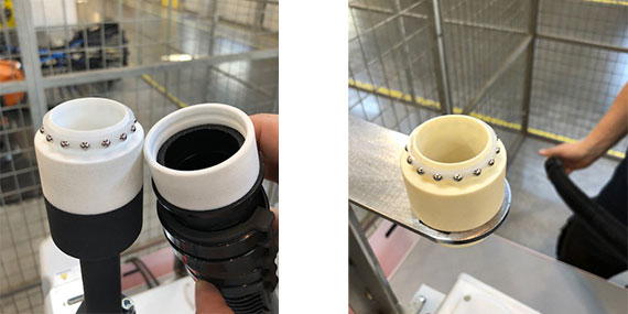
With the claim of developing everything ourselves as much as possible, and to fall back on our igus plain bearing knowledge, we decided to use balls from the xiros range in combination with our 3D printing service for the rotary connection. In addition to smooth running through the balls, another major advantage is the significantly lower weight of the polymer rotary connection. To test as many options as possible, we decided to use 2 different 3D print filaments on the first try. On the following pictures you can clearly see that these are parts from the 3D printer and the colour also indicates different materials. The aim is to produce the later series-ready bearing as an injection moulded part. At this stage of development, 3D printing is simply unbeatable in terms of time and cost.
Let the test games begin
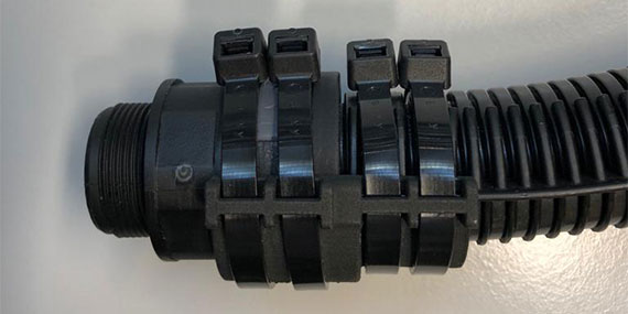
Before the first test run, the actual Scara solution had to be assembled from the individual parts such as the corrugated hose, e-rib, end connection support, rotary union, arch support and connecting brackets. The following picture shows one side of the Scara solution in close-up. This consists of:
- Screw mounting bracket (left)
- 4 cable tiewraps (centre)
- e-rib (right down)
- Corrugated hose (right, partially enclosed by the e-rib)
- End connection support (down)
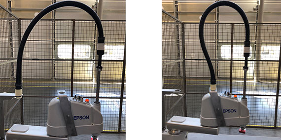
Finally, the first tests can begin and we only have to clarify which connection we are testing first. There was a choice between the connection between the rear bracket and the ball screw and the connection near the control panel and the ball screw. On the following photo you can clearly see that the degree of difficulty will be somewhat higher due to the proximity of both attachment points to each other. (Right photo)
When choosing which connection to test first, we didn’t let luck or the dice decide, but strictly according to the motto: “If one holds, then the other will also certainly hold. This selection may not be 100% in line with the usual test procedure, but it seemed plausible to us at the time to start with the more difficult of the two connections. In this case the disappointment in a crash is also not so big. The following video shows the first test cycles. The tension is great and we think we have already identified the first weak point.
What do you think this weakness could be? Just write it in the comments section.