Scara solution: From the idea to the product Episode 2
Marius Glaue | 29. July 2020
The package from Epson has arrived
“Is it Christmas already?” or “Huh, I didn’t order anything?” This is what comes over your lips or at least through your head when the call comes from the incoming goods department: “Your package has arrived.” This or something similar could have happened with the arrival of the G6-553S Manipulator RC620, which we received from Epson Germany for testing purposes in order to develop a production-ready Scara solution.
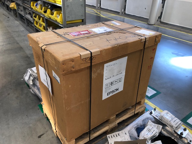
A place was quickly sought in our 3,800m² test laboratory in Cologne. Here is a small overview of our test laboratory, which at that time was still somewhat smaller at 2,750m². Before bolting the robot to the table, it made sense to check that the delivery was complete. However, the temptation to commission the plant without prior testing of the individual parts supplied was extremely high. The next picture shows that we kept a cool head after bolting the robot to the table and decided to check the delivery note. As expected, the delivery was complete. Thank you, Epson!
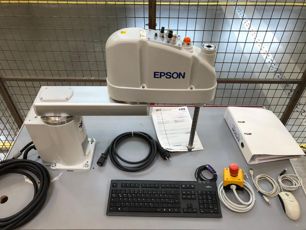
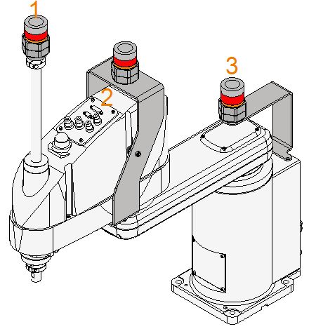
After the first functional tests of the robot we took the measurements for the first design. The aim is to develop an energy supply system suitable for use in mass production between the rear mounting point (3) and the ball-rolling screw as well as a connection between the ball screw (1) and the control panel on the robot (2). Both connections have their pitfalls, and what these are is shown in detail in the following sections.
The No. 1 challenge
Find the right turn
In episode 1 you will see how our automotive customer from the Swabia region implemented the connection between 1 and 3 with a self-built rotary connection and some other small adjustments. We would also like to develop this rotary connection for the series product. The difficulty is that, on the one hand, it should be very easy to turn and, on the other hand, it should be possible to fix it on both sides by bolting. We solve the problem of easy turning thanks to our extensive experience in the field of plain bearings. The following picture 4 shows the first drafts. On the left side of the picture you can see how the rotating connection is to be attached to the holder. Which brings us to the No. 2 challenge.
The No. 2 challenge
Material thickness and fixing points for the holders
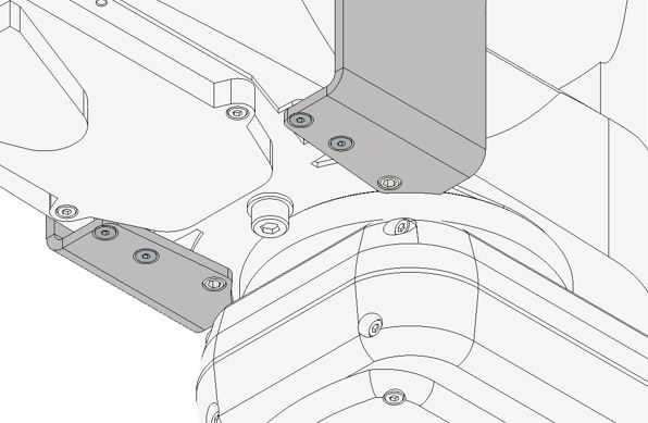
As can be seen in picture 3, unfortunately it is not always possible to install an additional mounting on the robot. In the first attempt we decided to fix it from below with the help of an extender crossbar (see picture 5). Here it is important to pay particular attention to the material thickness in terms of weight and possible vibration behaviour. We admit that we are not yet 100% satisfied with the current solution. Please write your ideas in the comment box. In addition, the type of mounting of the rotary connection had to be determined. Two options were shortlisted.
- A u-shaped connection for easy assembly and disassembly of the system with connectors
- Closed connection that offers more stability
To save weight and possibly make it easier to replace the entire Scara package, we thought the U-shaped bracket would be an elegant solution. There the package would have been pushed in from the side and jammed. Due to the high dynamics we decided to go for a completely closed version as shown on the left side of picture 4. This has the big advantage that the fixing is much safer but unfortunately there is also a big disadvantage: the cables and plugs have to be led through this eye of the needle when dismantling and installing a new Scara system.
The No. 3 challenge
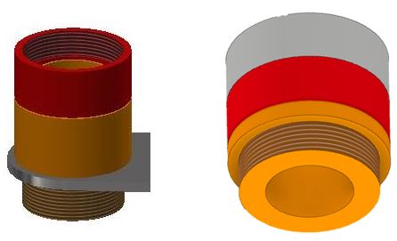
How do we get the Sub-D connector through?
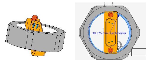
During the connection between the ball screw (1) and the control panel (2), we noticed the Sub-D connections and we realised that the dimensions of the rotary connection must be at least large enough to be able to use this type of connector without problems. As picture 6 shows, this was unfortunately not the case and we had to adapt the inner diameter of the rotary union to the outer dimensions of the Sub-D connector. it was necessary to find a compromise between the material thickness of the screw connection and a trouble-free feed-through of the connector.
In the next episode we will clarify what picture 7 is all about and what progress we have been able to make in the meantime or whether it has perhaps developed quite differently.
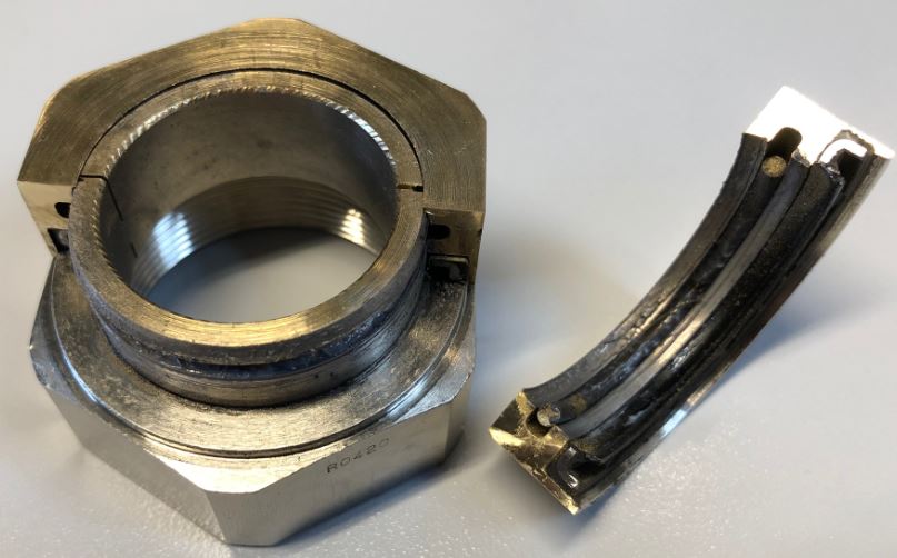
Stay tuned.