Motor alignment on igus axis – this is how assembly works
Adriana Glazer | 29. September 2020
Anyone who has ever wanted to order an igus linear axis is inevitably asked at some point what orientation the motor should have. Left, centre, right, 0° or 90°? It all sounds like choosing your party before the local elections, but it is much easier than that.
What is meant by motor alignment?
By motor alignment we mean the alignment of the electrical connections for, e.g. motor, encoder or brake connection. We define the alignment in degrees (looking at the motor from behind). For our well-known two “large” axis types we distinguish between the lead screw and the toothed belt axis. We also want to start with this and at the end there are our special alignments “radial kit”.
Toothed belt axes
This includes all axes with the types: ZLW, ZAW, ZLN and ZLWT Main feature, who would have thought it, is the drive type of the carriage. With this type of axis, this is accomplished with a toothed belt.
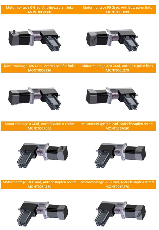
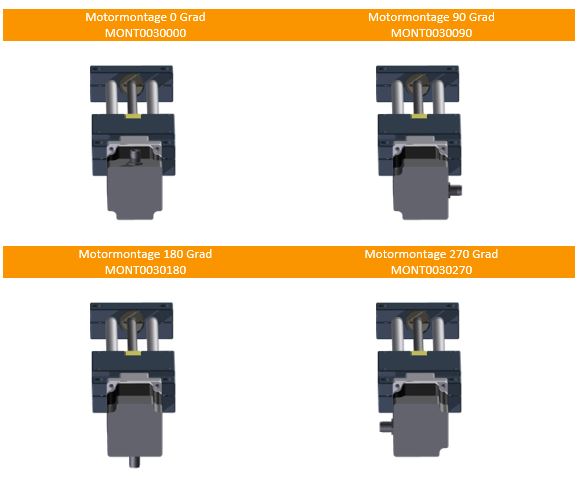
Lead screw axes
For our lead screw axes, the carriage is driven by a lead screw. Read more about our lead screws here .The lead screw axes include all axes with the designations: SLW, SAW, SHT, SHTC, SHTP, SLN and SET.
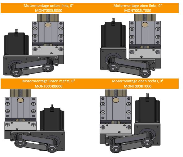
Radial kit
Now finally, as promised, the definition of our radial kits. These are almost exclusively attached to our linear axes. In special cases, such assembly is also conceivable on toothed belt axes, but this represents the absolute individual case. In order not to go beyond the scope of this article, I will not define the degrees here. The following pictures always show the motor orientation 0°.
A small Note: motor alignment 270° is not recommended here because of the danger of crashing with the axis
Well, the whole thing is very simple, you just need the right pictures.

Do you have any questions?
Send us your contact request here
Our experts will help find a solution for you.