What energy chains are there? Arrangement and tips
jhang | 16. July 2021
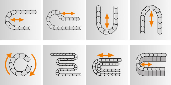
The various arrangements and installation variants for an energy chain are as follows: unsupported, gliding, hanging, standing, and rotating.
This article focuses mainly on the unsupported, gliding and hanging arrangements. It will give you an overview of the various energy chain arrangements and tell you what to look for during design to ensure a long service life and optimum profitability.
Unsupported energy chains
Unsupported energy chains offer the longest service life and can be operated with the maximum speed and acceleration values. Almost 95% of all applications can be covered with unsupported energy chains – with travels of up to about ten metres.
An unsupported energy chain is one in which the upper run (the guided upper part of the energy chain) does not touch the lower run over the entire travel.
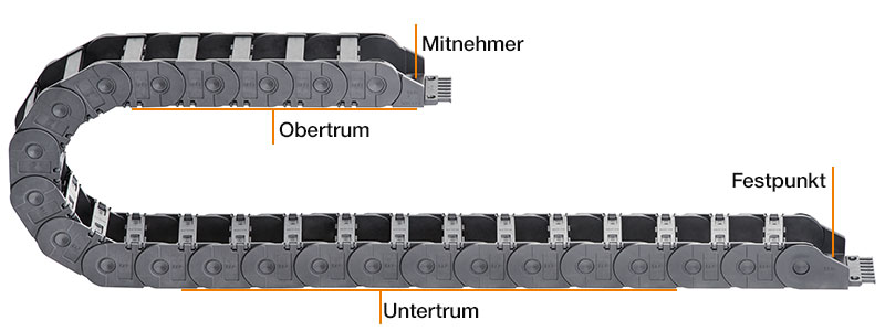
The unsupported length (FL)G is the distance between the moving end and the beginning of the energy chain’s radius curve, along which the energy supply’s upper run exhibits negligible sag. The maximum unsupported length varies according to chain type (series) and fill weight.
The unsupported length has three distinct stages:
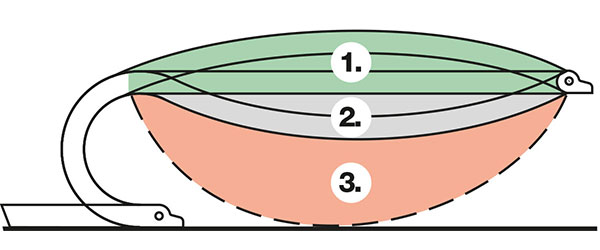
- Straight unsupported lengthG:the energy chain has a preload or is straight.
- Unsupported length with sagB:the energy chain has a sag of more than one half e-chain height.
- Critical sag:the sag is greater than the permissible value for the unsupported lengthB. Installation with critical sag must be avoided.
Special features:
Energy chains can be unsupported for a short travel only and are intended to have preload.
Accessories:
Mounting brackets
Mounting brackets are components that are attached to the end points of the energy chain. We recommend pivoting mounting brackets as standard for unsupported energy chains.
Ten tips for durable energy supply systems in unsupported applications
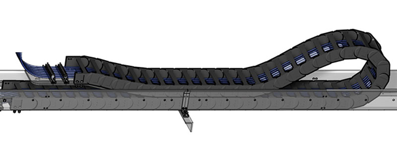
Gliding energy chains
A gliding energy chain is one in which the energy chain’s upper run runs on the lower run along the travel. Gliding energy chains are commonly used on long travels.
Technical details:
| Speed [Vmax]: | 10m/s |
| Acceleration [amax]: | application-dependent, can be 50m/s2+ |
| Max. travel: | up to 1,000m |
| Max. fill weight: | application-dependent, can be 70kg/m+ |
Installation type:
Gliding arrangement on one side
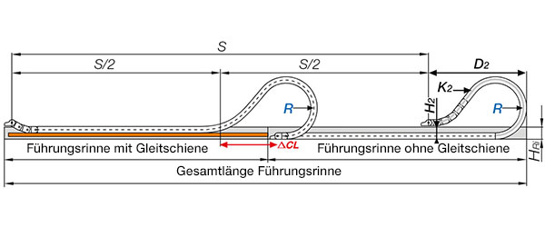
The fixed end of this arrangement is located in the centre of the travel. The centre infeed enables you to achieve the minimum energy chain length and the maximum cable travel.
Reverse gliding arrangement
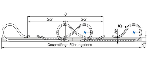
Configuration involving two reverse energy chains. The entire travel is designed in this manner. For use in tight spaces or with high loads.
If the stationary mounting bracket and the fixed cable ends can be placed in the centre, the e-chain® length is calculated as follows: LK = S/2 + K
Special features:
Unlike unsupported applications, maximum speed and acceleration are restricted. For optimal power transmission in a gliding arrangement, the energy chain’s moving end is lowered and the first chain links rotated. The moving end connection is generally at an angle of 3-5°. Gliding energy chains usually run in a guide trough so that the upper run rests without offset on the lower run.
Travel speeds and accelerations:
Travel speeds of up to 6m/s in continuous operation are possible and currently in use. Even higher speeds are possible in special cases. For example, energy chains from the E4 system achieve speeds of 22m/s and accelerations of 784m/s2 in crash test units. (Only a few thousand cycles per year are required in this situation.) Acceleration plays a crucial role in calculating the necessary service life.
Accessories:
Mounting brackets
A pivoting mounting bracket is considered necessary for gliding applications, since it is necessary in every gliding application to lower the moving end and angle the mounting bracket. This prevents the upper run from rising.
Guide troughs
Guide troughs allow energy chains to continue smooth, low-friction operation on long travels. Ensure that guide trough height is at least twice that of the energy chain. The sides must provide a chamfered basket towards the top. On the side of the trough, where the upper run cannot glide on the lower run, glide bars must be installed.
Thirteen tips for durable energy supply systems in gliding applications
Hanging energy chains
In hanging energy chains, energy chains are fixed or hung in the direction of movement. Hanging energy chains are used in fields such as material flow engineering or in construction and crane lifts.
Technical details:
| Max. stroke height: | 100m |
| Speed [Vmax]: | 20m/s (dependent on stroke height and stability) |
| Acceleration [Vmax]: | 50m/s2 (dependent on stroke height and stability) |
Installation types:
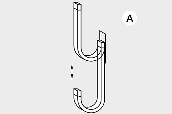
Without lateral acceleration:
Diagram A: Vertical motion without lateral acceleration usually requires no guidance .
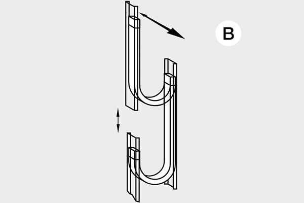
With lateral acceleration
Diagram B: Lateral acceleration can occur in two directions. Guidance is necessary.

With lateral acceleration
Diagram C: Lateral acceleration can occur in two directions. Guidance is necessary.
Special features:
Movement without lateral acceleration
If the application has purely vertical movement without lateral acceleration, the energy chain needs no lateral support.
Movement with lateral acceleration
If there is additional lateral acceleration, the energy chain will need lateral guidance in most cases. Guidance need not always be continuous. But it must cover the areas in which the energy chain might sway.
Lateral acceleration is then perpendicular to the energy chain where it is more stable. If guidance is used, an energy chain with preload should be selected. This ensures that the energy chain is pressed into the guide trough.
If possible, the energy chain installation in Diagram B is preferred.
For hanging arrangements, we recommend the guidelok vertical, E4.1 and E2/000 systems. For connection, we recommend using fixed mounting brackets as standard. The cables and hoses must have strain relief from both sides and must not touch the e-chain®. So they have to bear their own weight.
Nine tips for durable energy supply systems in hanging applications
Service life:
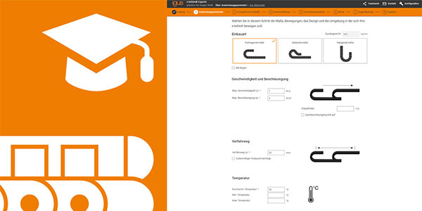
Because we perform 10 billion energy chain cycles in our 2,147m2 e-chain and chainflex test laboratory, we can make reliable predictions about the expected service life of our energy chains. The service life of our energy chains can be calculated quickly and easily with the service life calculator.


How support trays get the most out of your energy chains – igus Blog
[…] that adhere to each other or roll or slide past each other. Among them are energy chains (find out more about types of energy chains here) that guide cables and hoses in machines and systems. If e-chains run on an uneven surface, the […]