The issue of resistance
Nils Jäger | 27. April 2023
Most people remember the term resistance from physics lessons. In electrical engineering, on the other hand, the term is not only common, but also important for understanding. With regard to cables, too, it is important to take a closer look at the topic of resistance. In today’s post we will look at the issue of resistance and the correlation between cables and resistance.
The resistance
Let’s start at the beginning. In the basics of electrical engineering, one learns that there are electrical charges. When they move, we get electricity. The electrical voltage provides the drive. If the movement of the charge is impeded, we have resistance.
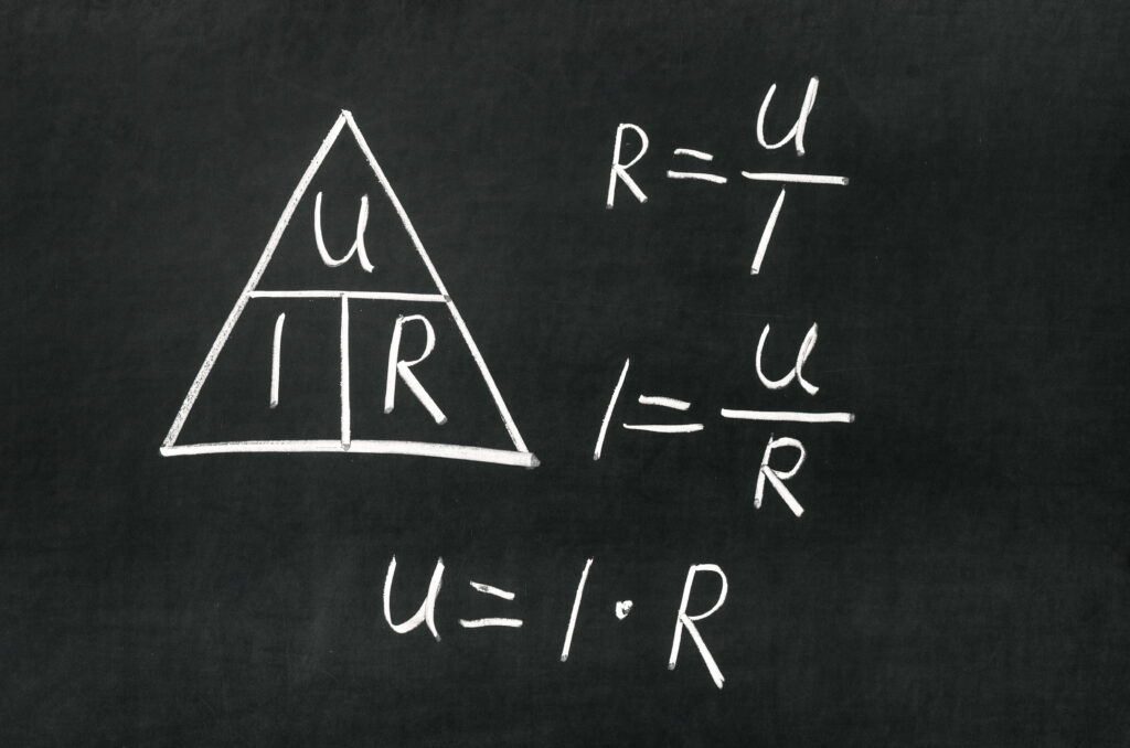
So there is a relationship between current, voltage and resistance. Basically, the resistance of a component indicates how much the electric current is impeded in it. The symbol for resistance is R. The unit of resistance is ohms. This correlation is established with Ohm’s law.
Which types of resistance are relevant for cables?
Conductor resistance – resistance of the copper conductor
The conductor resistance depends on various factors. For example, the length is relevant, just as the cross section and structure of the conductor. The conductor material used also plays a role, e.g. copper has a different conductivity than aluminium.
This conductor resistance is specified in DIN VDE 0295 for each cross section. Since the conductor cross section of cables is defined by the electrical resistance, we speak of the electrical cross section.
The mechanical or optical cross section can therefore deviate from the electrical cross section. This depends on whether the conductors are solid, multi-wire, fine-wired or even super-fine stranded wire conductors. In electrical engineering, however, the mechanical cross section only plays a subordinate role, since conductivity is more relevant here.
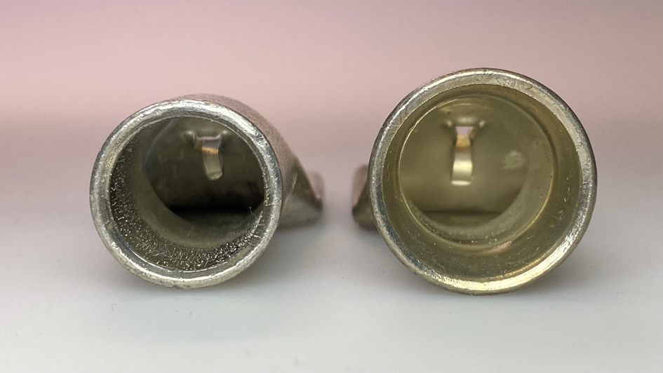
Installation materials, e.g. wire-end sleeves and compression cable lugs, are also designed for the electrical cross section, just like the conductors for which they are made.
This can be seen particularly well if you place cable lugs for multi-wire conductors and for extra-fine-wire conductors next to each other.
Insulation resistance – resistance of core insulation
The insulation resistance of cables is specified in Ω/km, as this depends on the length. In the ideal case, insulation has an infinite resistance in order to provide the greatest possible safety against short circuits.
This is only theoretically possible. A minimum resistance of 1 MΩ/km is therefore specified in DIN VDE 0100 Part 600. In general, the shorter the cable length, the higher the measured insulation resistance. The insulation resistance can be in the GΩ range for short cables.
In addition, the insulation materials used also influence the level of the insulation resistance.
Characteristic wave impedance/Cable impedance
The cable’s characteristic wave impedance describes the ratio of the current and voltage waves propagating in a common direction. The characteristic wave impedance depends on the frequency and basically affects every cable. You can see the correlations very well particularly in bus cables.
In order to prevent reflections of the signals to be transmitted during bus transmission, it is important that a specific characteristic wave impedance is defined so that the end of the cable can be terminated accordingly. If this is not done, transmission errors can occur which can even lead to failure of the respective bus system.
Depending on the bus system, the required characteristic wave impedances can be different. For a better understanding, here are some examples:
- Ethernet, Profinet, EtherCat 100Ω
- Profibus 150Ω
- CAN bus 120Ω
- CC-Link 110Ω
- USB 90Ω
Conclusion
A cable is also an electrotechnical product that must be designed to suit the application. Moving cables pose an exceptional challenge, as the movement changes the position of the cores in relation to one another, as well as to the centre of the cable. This has an effect on capacitance and thus also on the characteristic wave impedance. The cores of a moving cable can break at some point due to the permanent strain. However, this happens gradually. The result is a constantly increasing conductor resistance and thus also an increasing voltage drop. This also affects the signal to be transmitted.
Do you need help selecting a suitable cable for your application? Talk to us or visit us at www.igus.eu/chainflex. In our online shop you will find all the relevant data about our cables, e.g. data sheets.