Standing installation of energy chains in machine tools
mkogelmann | 31. March 2020
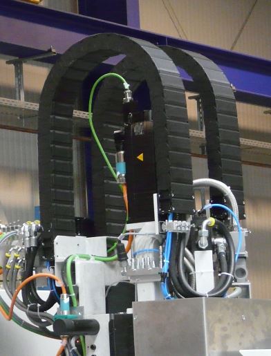
Whether in handling systems or in machine tools, with vertical movements the energy supply systems must often be planned “standing”. Actually not a great challenge, but there are still some aspects that have to be considered and taken into account during planning and design.
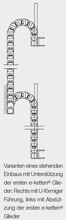
Pivoting or locking mounting brackets?
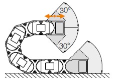
If I can support the e-chain on both sides in the outer radius, pivoting mounting brackets can be included. These offer the advantage that with limited installation space, the dimension for the chain station (dimension “D” in the catalogue specifications) can be reduced by about one chain link length.
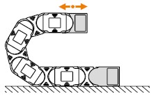
If I cannot provide support for the outer radius of the e-chain, a rigid mounting bracket must be planned. Of course you can also “mix”, depending on how your respective ambient construction looks.
How much installation space do I need horizontally?
The minimum required installation space results from 2x radius + chain height. Depending on the chain size and radius, it is advisable to provide some additional space (20-30mm). It is also often recommended to order the e-chain WITHOUT pretension. To do this, simply add a “.NC” to the part number of the respective energy chain, e.g. 2500.05.075.0. NC.
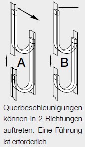
How you deal with transverse forces?
If the energy chain is installed on a carriage that travels transverse to the installation direction of the e-chain, this must additionally absorb the acceleration forces that occur. To avoid overloading the e-chain in such cases, lateral support plates must be provided. Depending on the occurring forces, length of the e-chain, additional fill weight and length of the support must also be selected. Particularly suitable for such applications are e-chains series with undercut design.
How should cables and hoses be laid and strain-relieved?
These two points are important and require special attention. All cables and hoses must be strain-relieved so that they can bear their own weight and do not slip. The energy chain serves only as a guide element, but does not assume any support or holding functions.
Suitable strain relief elements here are igus CFX clamps, CFB strain relief plug-in system or tiewrap plates.
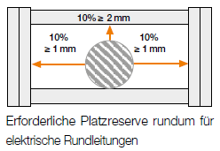
All cables and media guides must be laid neatly separated from each other, and the space requirements must be observed as in other installation types.
For electrical cables, plan 10% of the cable diameter, but at least 1mm as free space on the left and right, as well as 10% or at least 2mm over the electrical cable. For hydraulic hoses it is at least 20%.