Is the unsupported lower run the solution to all space problems?
Volker Beissel | 1. February 2021
A gantry design is frequently found in machine tools in particular. In addition to large machining centres, particularly in sheet metal working machines such as laser or plasma cutting systems. In the last few weeks, there have been several requests that the energy supply system should not have any influence on the overall width of the machine. In other words, the biggest and heaviest chain is to be removed. The goal is clear: a compact design in which the working space area is as close as possible to the footprint of the machine.
But where to put the chain?
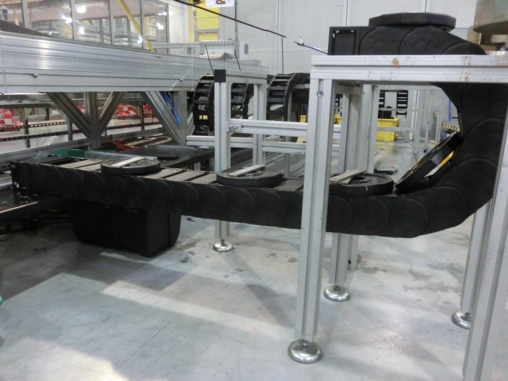
Of course, under the machine roof. Simply fix the fixed end under the ceiling and let the moving end move along at the bottom of the cross beam. This way, the x-chain no longer takes up space next to the guide rail and “floats” above the work surface. This works without any problems, at least in theory. In practice, a completely new application arises, namely that of the unsupported lower run.
But what does unsupported lower run mean?
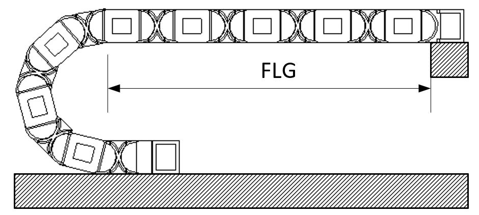
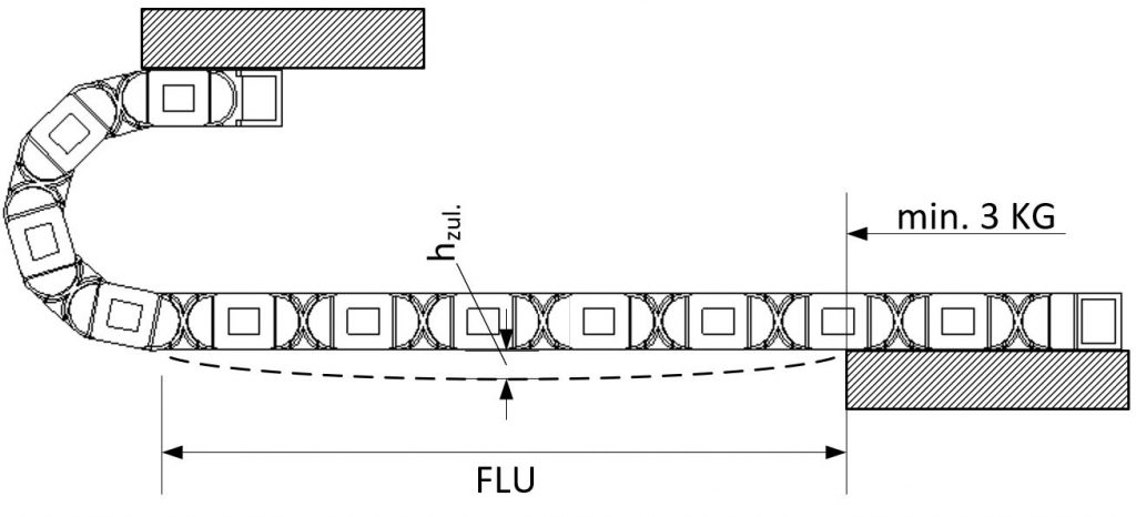
In most applications, the chain lies on the bottom of a sheet or, better, in a trough. The fixed end is then bolted at the bottom and the moving end moves above it. This is then done unsupported (FLG – unsupported with straight upper run) or, in the case of longer travels, gliding. The igus catalogue specifications are designed for this “normal case”. If the fixed end is now at the top and the moving end travels at the bottom, the result is that the chain is no longer supported in the lower run, i.e. it is unsupported. This significantly increases the load on the mounting brackets and the chain as a whole. The familiar graphs for unsupported length and travel therefore no longer apply.
How do you know if your application is possible with unsupported lower run?
Of course, we also made countless tests on the unsupported lower run. To be sure that the selected energy chain will last as long in your application, you can contact your igus representative. Based on our test data, the igus contact person can then predict the feasibility and service life as usual.
The following five tips can be used as an initial assessment of feasibility:
1. At least the first three chain links of the lower run should be supported to reduce the force on the mounting bracket.
2. Supported chain links do not count as part of the FLU area.
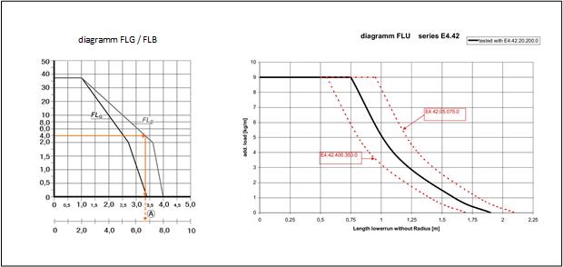
3. The maximum unsupported length of the lower run is approximately 50% less than the length of the unsupported straight from the catalogue.
4. The maximum fill weight is around 30% of the fill weight in the case of the unsupported straight.
5. For FLU applications, the maximum unsupported with permitted sag speed and acceleration specifications from the catalogue apply.
In summary, this means that the standard design cannot simply be replaced by a “floating” chain. For short strokes up to 2m, however, it can be an attractive alternative to create more space with the same machine dimensions.
My tip: on the machine tool industry page there is a compact overview of the right products for your machine. https://www.igus.eu/info/industries-machine-tool-industry?L=en