Design tips: multi-material parts from the 3D printer
Niklas Eutebach | 30. March 2020
Additive manufacturing and new types of production
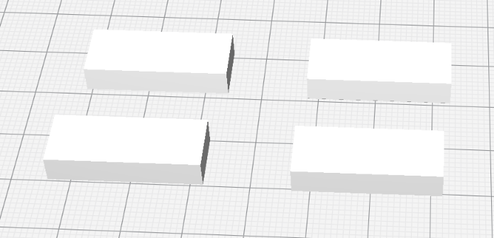
Most development departments, production lines and workshops can no longer be imagined without additive manufacturing. While in the beginning the technology was mainly used for prototypes and view models, both plant technology and the materials developed more and more; for example, in the field of engineering plastics, the major polymer specialists have been pushing 3D printing materials onto the market in recent years. This enabled more and more functional applications. The comparatively simple plant technology and handling are a decisive reason why there is probably the greatest material diversity in 3D printing processes in the field of 3D print filaments.
Even igus, which has always been involved in the development of functional high-performance polymers, took up additive production several years ago and developed materials for filament printers (FDM) and laser sintering printers (SLS). Accordingly, this article deals with materials for moving applications in which friction and wear occurs in contrast to static components.
Multi-material 3D printing
While on the one hand, design offices are considering how additive manufacturing could be used in the most sensible and profitable way to replace or supplement existing manufacturing techniques, on the other hand, manufacturing technology is rushing ahead of product development with the possibilities it offers. We are talking here about multi-material components, sometimes referred to in German as 2-component parts (2K). This refers to the possibility of manufacturing a component from two different materials in one production step, i.e. without subsequent joining.
For procedural reasons, processes that produce components from the liquid or powdered raw material have not offered this possibility so far: it is reserved for 3D printers that work according to the melt strand deposition method (FDM/FFF). This is because of the method used: the raw material – filament – is applied through a melting nozzle, of which almost any number can be arranged on one or more print heads. The second nozzle on the print head is usually used for processing support material that does not remain on the component after printing. However, different filaments can also be combined in this way to form one component.
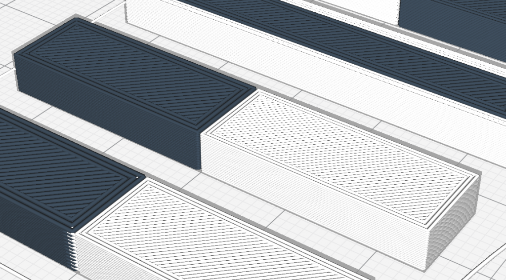
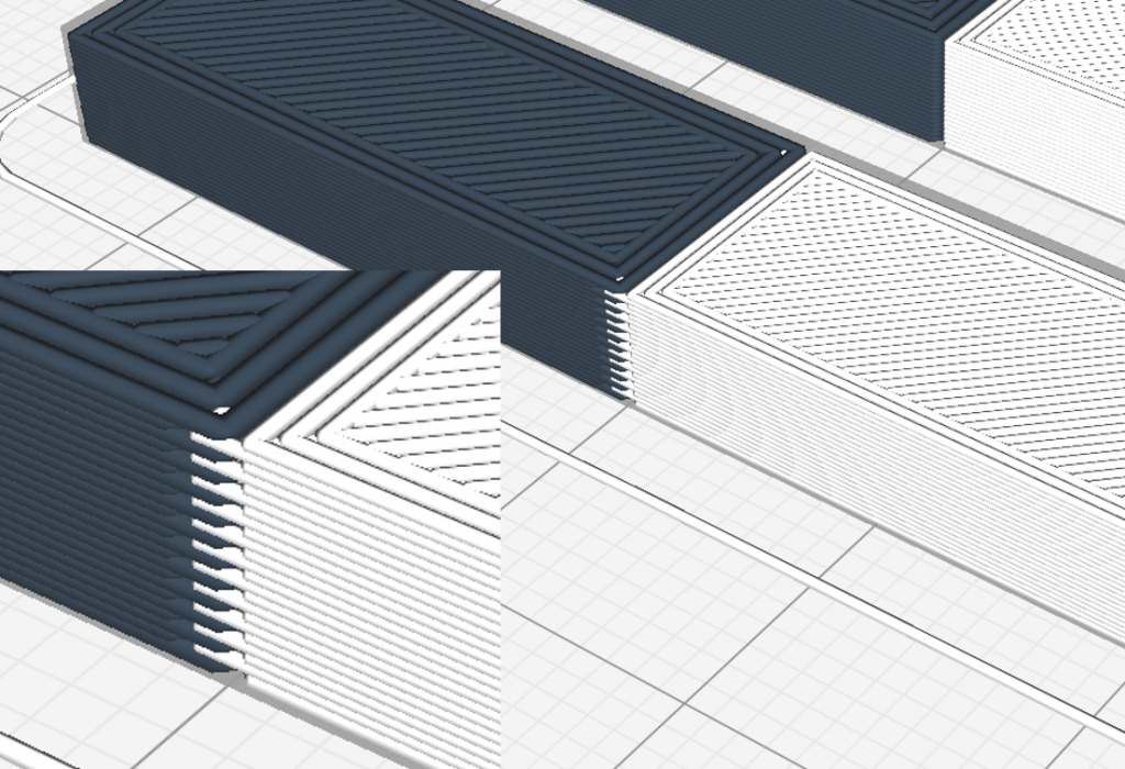
Since the 3D printer switches between the two materials in each layer in this process, there is no geometric restriction on how the two “phases” (analogous to chemistry) can be combined. In this way, the materials can be interlocked, enclosed, alternated in layers, etc. Depending on the 3D printing software (Slicer), different features (such as infill, outer skin, top and bottom) can be assigned to one or the other material, so you can be very creative in combining the materials.
Combination options of different materials
Filament diversity
To appreciate the potential of this manufacturing option, one must first consider the variety of materials that 3D printing with filament offers. Without claiming to be exhaustive, an overview of the different types of filaments or the functional specifications that can be purchased with a particular filament is provided here:
- Optics: filament in various colours (up to special designs according to RAL colour) and surface finishes (glossy, matt, translucent), metal filled
- Mechanical specifications: tough, temperature-resistant, fibre-reinforced, flexible
- Special features: fire-retardant, antistatic or conductive, tribologically optimised, foaming
As already described, two filaments can theoretically be combined as desired on a standard printer. At most, significantly different processing temperatures have a restrictive effect. The materials do not necessarily have to fuse with each other at the boundary layers either, since an inseparable connection between the two phases can still be achieved by a constructively resolved form closure of the two materials.
Ideas for applications
The following ideas for sensible and functional material combinations are briefly presented:
- A component for deflecting forces in an apparatus should have the highest possible stiffness to keep the joint free from interference. At the same time, the bearings should be as smooth-running as possible, and should be durable and wear-resistant.
-> A good combination here is a structural material reinforced with glass or carbon fibres such as igumid P150 and a tribologically optimised material such as the igus® iglidur® tribo-filaments. - The dynamic requirements dictate that a gripper element be as light as possible, but with great flexural strength, and grip securely but gently.
-> While the gripper’s body is manufactured with a fibre-reinforced filament, a flexible filament can be used for the gripping surfaces, which provides a secure grip through a high coefficient of friction. - A shaft’s bearings should compensate for any angle errors and dampen shocks.
-> The plain bearing element consisting of tribo-filaments can be encased with a flexible filament such as TPU with a Shore hardness of 95 A.
Requirements for the combination of different materials
Two different filaments can be joined together in different ways to form a durable component. On the one hand, the materials are fused or “welded” in the interfaces similar to the way they are done between two layers of the same material. This works better, the more similar the filaments are in terms of polymer composition and processing temperatures. But even less similar materials enter into a certain degree of bonding. Limits are only set here, if the processing temperature of one material exceeds that of the other to such an extent that the second material can no longer be processed with dimensional stability or even decomposes.
On the other hand, a form-fit design of both phases allows a connection to be made which cannot be released without destruction. There are different approaches to this, which are explained in more detail in the following section.
Construction for multi-material 3D printing
Implementation in CAD system
If you want to start 3D printing of multi-material parts, the first question is how to teach the 3D printer where to use which material. Using the software and hardware used at igus as an example, we will show how to proceed here. For the design the Autodesk Inventor is used, a new-generation Ultimaker as a 3D printer with two material nozzles and the matching slicer software Cura in its latest version.
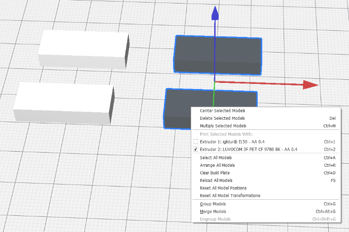
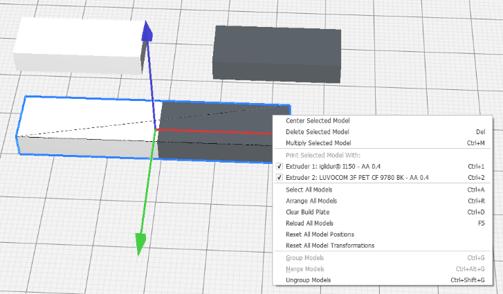
Cura offers the possibility to superimpose STL models. Here, two models are combined in such a way that their coordinate systems and origins match. Furthermore, materials can be individually assigned to the models. A 2-component part requires two STL models that belong together and to which the respective material is assigned.

There are several ways to achieve this in the CAD system. However, the simplest and preferred method is to design a component with several solid bodies. Boolean operations can be used to ensure that the solids fit neatly into each other and do not overlap. If the objects are then exported individually in STL format, the above-mentioned requirement is fulfilled: in the CAD system, both models refer to the same co-ordinate system, and can therefore also be neatly superimposed in Cura.
The graphic shows how the different filaments are assigned to the models and how the models can then be combined into one component.
Connection of the two materials
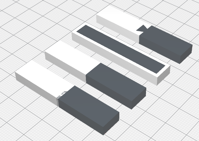
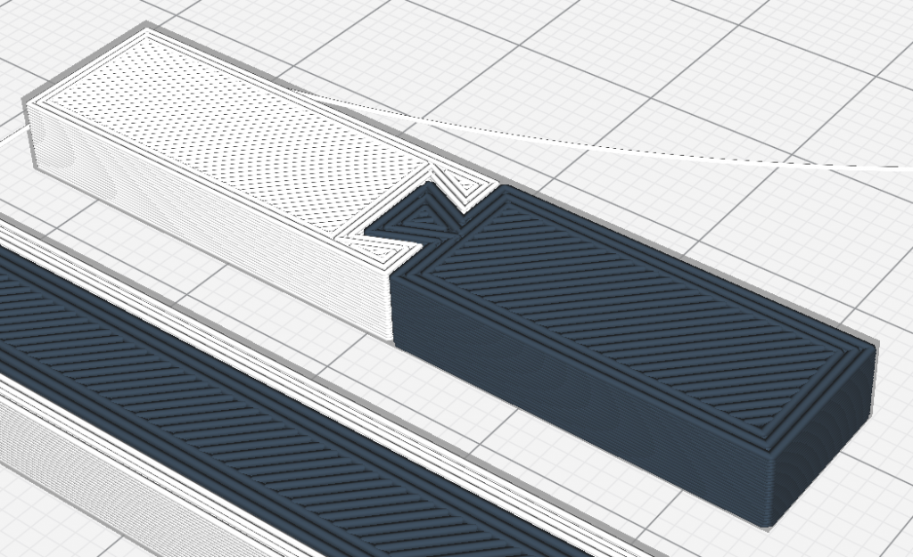
As already mentioned, a connection between two materials in a component can be made with a positive fit and a material bonding. A positive-locking connection is of course also a material-locking connection, but offers greater security against failure. In the following some examples of positive fit and material bonding connections using suitable design and implementation with Cura are shown. The simplest material bonding connection is the direct joint without overlap. Positive-locking connections can be created by a dovetail, for example – however, there are practically no limits to the design, and often the geometry is determined by the application anyway.
Tip: when slicing (creating the layer geometry), Cura prefers one material alternately in each layer, then the other material first. As a result, if the models overlap, there is an effect at the boundary layer, which can be seen in the graphic: the layers alternately overlap each other, thus interlocking the phases and significantly strengthening the bonding. This effect can be used in a well-dosed way; for example, you can design the solids “zero to zero” in the CAD system and thicken one of the bodies at the points where you want to achieve an overlapping, so that the models overlap.

Execution in 3D printing
Very simple – once the filaments selected in Cura are loaded accordingly on the Ultimaker, the construction job simply has to be transferred to the printer. There is nothing else to consider.
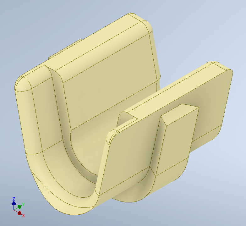
Application example from the practice
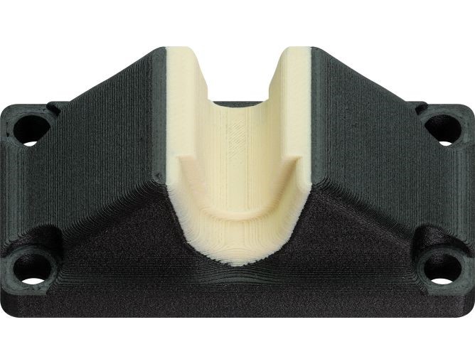
The example shown here is a lead screw support block on which a shaft is mounted so that it can be easily removed (this is practical for the application). The main body of the component is made of fibre-reinforced filament, while the critical bearing surface on which the shaft runs, sometimes at high speeds, is made of tribo-filament. The bearing surface is provided with a concealed circumferential element for the form-fitting connection of both materials.
Multi-material 3D printing in the igus 3D printing service
Do you already have an idea how you can use multi-material 3D printing profitably, but don’t have an appropriate 3D printer? We would be happy to help you with the implementation. For combining with our tribo-filaments, which can be processed on an Ultimaker or similar 3D printer, we are currently able to process a carbon fibre-reinforced filament with a very high stiffness compared to standard materials, and furthermore a flexible filament with a Shore hardness of 95 A.