Construction and assembly of lead screw motors – the basics
Adriana Glazer | 20. November 2020
As a well-known manufacturer of engineering plastics, igus has meanwhile established itself in the minds of the engineering universe. But around these core products a huge product world has developed with over 10,000,XXX different products. One of them is the lead screw motor. As the name suggests, a lead screw motor consists of a lead screw and a motor … well, and a driven nut, but lead screw nut motor or motor with lead screw and nut sounds rather uncool and is not very marketable. Be that as it may, here and now everything revolves around the construction and assembly of lead screw motors and other things that need to be taken care of.
But what is a lead screw motor?
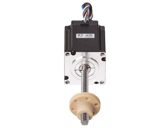
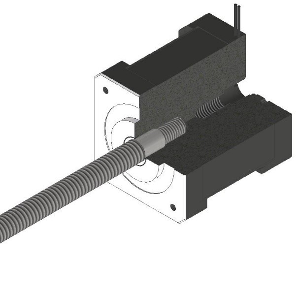
In its simplest form, an igus lead screw motor consists of a lead screw and a motor. In order to drive something, as a rule, a nut is needed. The whole thing is shown in the following picture.

The motor is designed as a stepper motor with hollow shaft. These motors are specially designed to absorb axial forces. Our NEMA23 lead motor can axially absorb for example 500 N. Conventional stepper motors would be damaged by this axial load. In the hollow shaft there is a holder for our lead screws so that they can be screwed and glued. This connection is so powerful that it can only be released with special tools and a specially developed process.
By the way: please do not try it yourself, the motor can be damaged in 9 out of 10 cases

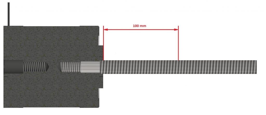
The motor can also be equipped with an encoder and/or industrial M8 connector. The lead screw has been specially machined for this motor so that the thread starts directly from the motor flange. There is therefore no loss of stroke.
Setting the correct screw straightness
Once the lead screw has been inserted into the motor, the lead screw is straightened. Here we distinguish between two different lead screw motor precision classes (igus in-house misnomer 2013):
- SMP 0.2 Concentricity of 0.2mm measured from 100mm of the motor flange
- SMP u non-directional without definition
Usually the SMP 0.2 is sufficient, but we are currently working on processes to ensure even better concentricity, but these are not yet fully developed. For very cost-sensitive applications, the SMP u can also be used to offer maximum savings.

Finding the right lead screw length
The definition of lead screw length is somewhat tricky, but nevertheless easy to understand:
- Lead screw length = total length incl. assembly pin and crank
- Unsupported lead screw length = lead screw length from motor flange without assembly pin and crank
- Stroke = unsupported lead screw length minus the length of the nut
In principle, all igus lead screws can be coupled with the motors, but nevertheless – as is actually always the case in mechanical engineering – common sense should be applied. 40mm lead screw with Nema11 (0.12Nm) certainly looks cool, but nothing more. Since the lead screws require special machining, we have a defined number of lead screw geometries in stock. These are cut to length as required. You can find an overview of available lead screws online or in our data sheet.
There is nothing special about our nut since it is basically about lead screw motors. Of course, you can also choose a nut from our standard range or request a specified geometry – as is usual at igus. We are happy to offer you an injection-moulded special nut according to your wishes and ideas.
The lead screw motors are packed in foam and delivered protected from external influences.
If you are interested in lead screw motors (or lead screw nut motors), please let me know. I will gladly find the right configuration for your application.
Continue reading: what can the D1 motor control system do?

Do you have any questions?
Send us your contact request here
Our experts will help find a solution for you.

