Locating spigot for bushings? This is how it works:
Lars Butenschön | 9. September 2022
There are many reasons for fixing bushings in the axial direction. If excessive forces act in the axial direction or external influences have a negative effect on the press-fit of the bearings, bushings are at risk of being pushed out of the bearing point. As a result, the shaft rotates in the housing hole “without protection” and is damaged. In order to prevent this, in addition to the press-fit, it is necessary in these applications to secure the bushing against the so-called “drifting”. Now that we have already looked at some concepts based on the shape of the bushing itself, I would now like to shed light on some design measures that can be performed on the housing hole. This can often be more cost-effective than designing a bushing with special geometry, especially in the early phase of the design process.
Option 1: Locating spigot with disc or flange
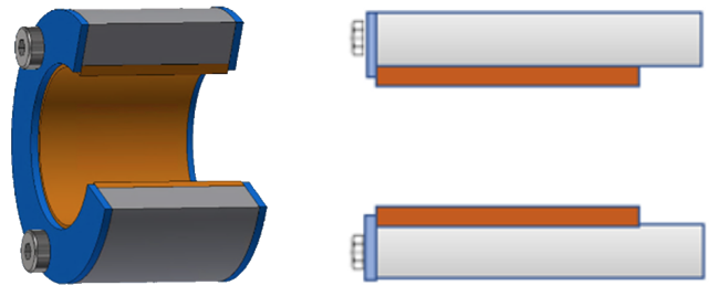
Depending on the design and number of bearing points, it may be sufficient to simply attach a disc against which the bushing can be pressed, or which additionally fixes it on the opposite side. Of course, you can also achieve the same effect with a flange in the housing hole.
Option 2: Securing with a circlip or snap ring
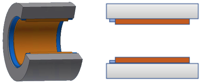
In this variant, a circlip is pressed in after the bushing has been installed. You can either work with two rings, in which one ring is pressed in front of the bushing and the other ring is pressed in after the bushing, or you can work with an opposite flange, thus saving additional installation effort. Of course, this variant can also be combined with variant 1. The metallic circlip can either be covered with a lid or mounted in a recess, which further increases the force required for unintended disassembly.
Option 3: Assembly via reduced diameter
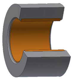
As a result, the diameter of the housing is further reduced as an undercut “inside” the housing hole, so that a narrow flange remains on both outer edges. During installation, the bushing is pressed over this constriction and securely fixed in both directions. This method naturally requires a certain flexibility of the bushing or the housing. Both this flexibility and the strength of the material of the housing hole influence the shape of the flange, in addition to expansion due to temperature and behaviour in long term exposure to moisture. However, these interactions and their influence on the resulting push-out forces are the subject of another blog post :).
Option 4: Locating spigot due to roughening of the housing hole

Roughly simplified and leaving out certain special cases in the science behind adhesive forces a bit, you may say: The smoother the surfaces of the bushing and the housing hole, the lower the press-fit. By roughening the housing hole, we were able to significantly increase the push-out forces. When comparing housings with Ra 0.4µm and Ra 4µm, we were able to, for example, determine a doubling of the displacement force.
Do you need help in securing your bearing bushings? We would be happy to assist you!
These were the most common methods for the locating spigot of bushings. All have advantages and disadvantages, are not necessarily suitable for all applications, can be combined with each other and designed differently depending on the nature of the bearing point and the bushings. With over 40 years of experience in the design and manufacture of plain bearings, we would be happy to assist you in this regard. Contact us!