Designing lead screw nuts for 3D printing
Paul Gomer | 24. April 2020
The two most common reasons for manufacturing drive and lead screw nuts using 3D printing processes are the construction of functional prototypes and the production of complex custom nuts. In product development, several models are sometimes designed and tested – with the rapid prototyping process, the production of near-series variants and customisations can be carried out very quickly, which enables a faster market entry. The production of complex customised nuts often involves a great deal of manual effort, which can quickly make such solutions very expensive. 3D printing technologies make it possible to reduce costs in this case – but this also requires a 3D model of the desired thread. Digital aids can facilitate and accelerate the design and customisation of individual threads.
Simple cylindrical (form S) or flanged (form F) geometries can be quickly and easily customised and downloaded in our CAD configurator for lead screw nuts. The metric thread sizes, based on ISO trapezoidal thread according to DIN 103, of series 1 and 2 are available. Finished configurations can be requested or ordered directly afterwards in the online print service, which speeds up the design and production process for customised lead screw nuts enormously.
Thread models can be configured conveniently at the beginning of the design process and downloaded in a native CAD program format. The downloaded file can be used as the basis for designing a complex special nut. Fully designed models can also be integrated quickly into the existing CAD file by combining volume models. An alternative which will be described below is adjustment in the CAD model (with the thread/spiral function, depending on CAD program).
How special lead screw nuts can be adapted in the native CAD program so as to be ready for manufacture
For a functional design, trapezoidal threads must be prepared for 3D printing. For laser sintering, this can be reliably guaranteed for the majority of standard trapezoidal thread sizes from TR8 by means of designed-in thread clearance. Compensation is necessary because internal holes (in particular small holes D< 3mm and deep holes t> 10mm) are otherwise always produced with a narrower diameter during laser sintering due to the higher heat input. This is due to the higher heat storage within the hole, which can lead to melting of the edge areas. [Source: Generative manufacturing with plastics conception and design through selective laser sintering: Breuninger, J., 2013]
The axial edge clearance in the Z direction must be increased by +0.1mm and the D1 and D4 diameters by +0.3mm.
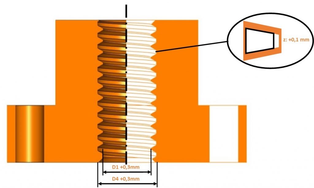
Principle representation of the adjustments to the CAD model
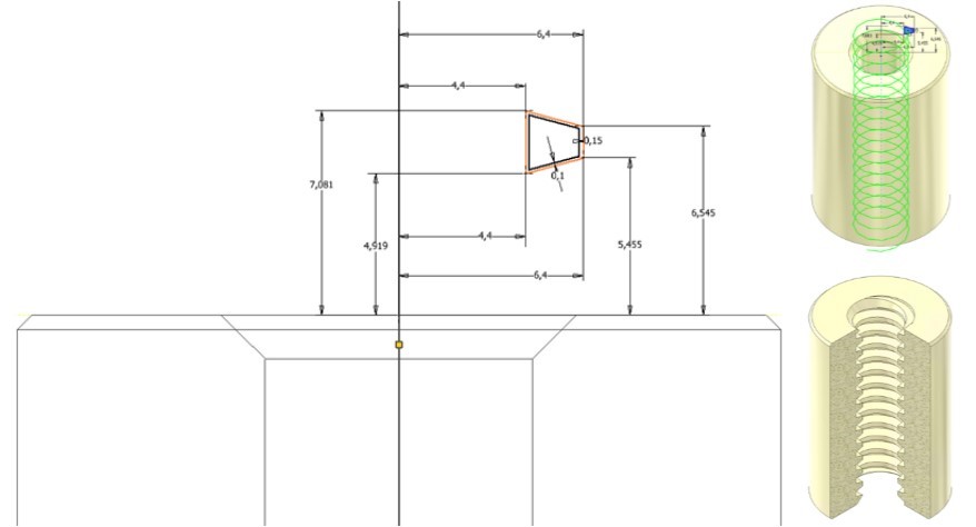
In practical application in the CAD system, this means enlarging the D1 blind hole bore by 0.3mm. The 2D sketch design of the thread profile must be according to the specification table and adjusted by the figures indicated. Radial clearance of +0.15mm must be added to the thread tip (to increase D4 to +0.3mm in total). Using the spiral or thread function, the trapezoidal thread can now be modelled by selecting the direction of rotation and thread pitch, cf. example image TR12x3.
What differences are there for the correct manufacture of a trapezoidal thread with 3D printing filaments?
For filament-based printing using melt strand deposition (FDM/FFF), printing parameters usually have to be adapted in addition to the design of the thread in order to prevent the nut from jamming on the lead screw. Among the suitable adaptations for printing parameters are the following:
- reducing the flow modifier factor/filament flow (about 5-10%)
- using lower thicknesses: 0.2mm or less
- avoiding support structures other than water-soluble support material (which can be used as necessary)
- testing the following printing parameters to achieve better precision at the X-Y level:
- Horizontal expansion: -0.05 to -0.1mm
- Alternative: activate outer walls before inner walls
It is recommended that a test print of a small thread portion be run before the entire component is manufactured. This greatly reduces adjustment cycles.
Areas of application for printed special lead screw nuts
The lubrication-free lead screw technology drive solution reduces maintenance work, reduces costs and extends the service life of materials used. 3D printing grants familiar advantages such as, great freedom of design (complexity does not impose additional costs), fast delivery times (1-3 business days), and economical manufacture with no minimum quantity.
3D-printed drive nuts made from iglidur filaments and laser sintering materials are also used in many industries:
- Automation/process technology, such as product handling in the packaging industry
- Machine/special machine construction (special drive nuts, for instance)
- Automotive industry, such as prototypes for mechanical locking systems
- Robot industry, such as threads integrated into gripping mechanics
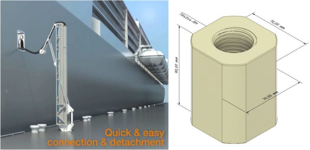
Application: how 3D printing can help with shore power connections for ships in just 48 hours
In order to reduce air and noise pollution in harbour cities and to reduce diesel consumption in the harbours themselves, many places use shore power supply systems for container terminals and ships to reduce CO2emissions. Three custom nuts with the trapezoidal thread TR40x14 were manufactured in just 48 hours for a shore power supply application and were then able to be installed in the harbour. As mechanically machined components were not available at short notice and a high delivery time seemed unavoidable, the production of the custom nut made of the iglidur i3 laser sintering material using 3D printing was an option. The urgently required custom nuts are subjected to a maximum static load of approx. 1200kg in the application and were able to be manufactured economically, without costly rework, for approx. 300 €/piece.
How can I get my 3D printed dryspin special lead screw nut
Custom nuts can be manufactured upon request, including for dryspin lead screw geometries.
The advantages of wear-optimised dryspin high helix threads over standard 3D printing materials, can be seen in the results of our laboratory tests on a DS14x25 dryspin lead screw nut with a stroke of 370mm and load parameters of 129N load at 290rpm. Wear can be reduced by a factor of 5 to 18 with tribologically optimised 3D printing materials.
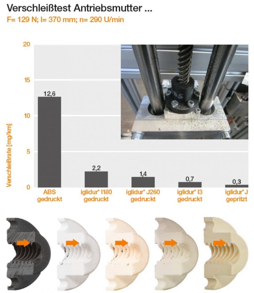
Drive nut wear results in the laboratory test: Standard 3D printed material ABS vs. igus tribo materials iglidur i180 / iglidur J260 / iglidur i3 printed and iglidur J injection moulded
If you are also looking for the right lead screw for your drive nut, you can configure it in our online shop without in-depth technical expertise or CAD software, together with the associated drawing.