The moving lower run
Lars Butenschön | 21. April 2020
Installation situation e-chain with moving lower run
Sometimes the installation situation requires turning the orientation of the e-chain and turning it upside down, so to speak.
The fixed end is mounted “up” and the moving end is “down”. This is a very special installation situation and places other demands on the design of the energy chain, especially if the lower run is not supported.
The normal load diagrams FLG and FLB, which we find in the catalogue, cannot be used for the design in these cases.
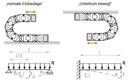
The installation position “normal” corresponds to a beam carrying line load. The one with “lower run moves” is that of a beam clamped on one side with line load. The torque introduced into the chain are many times higher here. This is also reflected in the load diagrams.
Here is an example of the E4.56 series
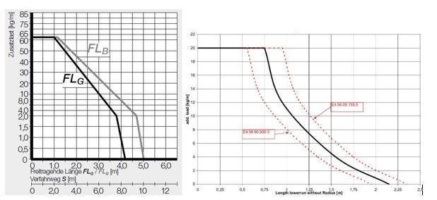
Example E4.56.100.200.0, 10kg fill weight. The maximum travel in “normal” installation position is approx. 6 metres, but only approx. 2.2 metres with a moving lower run.
The right choice of mounting bracket
A pivoting element can be selected at the fixed end. However, if a support plate is missing on the moving end in the outer radius, a locking mounting bracket must be selected.
The selection of the suitable energy chain
Here we must seek the advice of an expert. In addition to the usual technical framework conditions such as speed, acceleration, filling weight, etc. we must clarify further points here. Are supports for the lower run feasible? Support plates can be provided on the moving end and on a part of the energy chain in the outer radius. These two points, in particular, contribute decisively to the correct selection of the e-chain and can lead to the fact that we can make the dimensions of the chain smaller.