How do I replace my defective gear?
Niklas Eutebach | 26. March 2020
A tooth breaks on a gear, and that’s all it takes to stop the machine. Unfortunately, the documentation has been lost, and the manufacturer does not supply spare parts any more and may even have gone out of business. What now? The gear must be replaced, and there are no clues besides the broken component. And even if you happen know the gear’s parameters, the right gear isn’t among the usual suspects in the product range or requires rework before it will fit.
igus gear configurator and 3D printing service
The simple solution is the igus 3D printing service – individually created gears can be manufactured from wear-resistant polymer with no minimum order quantity, quickly and cost-effectively. You don’t even need a CAD system for the design, since igus provides the gear configurator for use free of charge.
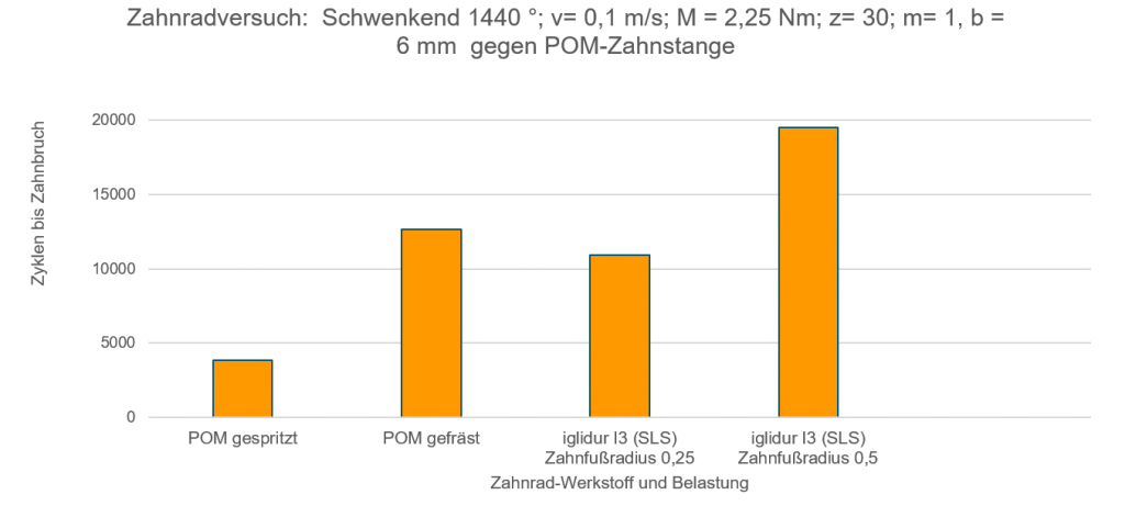
Thanks to the special iglidur laser sintering powder and the tooth shape optimised in this process, gears from the igus 3D printing service are as good as or better than milled or injection-moulded gears made of commonly-used gear materials. How do we know? Because of extensive tests in the igus test laboratory and the service life calculator based on the data they return. The calculator reliably determines the service life of printed gears.
Configuring a gear using just a few parameters
That sounds easy, but how do I get a 3D printed gear?
The igus gear configurator allows configuration of a gear model with correctly shaped involute geometry and rounded tooth root. Many CAD programmes simplify the process greatly, which can lead to rough running and early wear or gear failure.
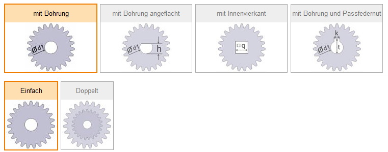
The configurator has several options for recreating an existing gear. For instance, various shaft shapes can be selected for torque transmission, and single or double gears can be created.
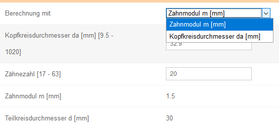
The tooth number and the gear module or head diameter (outer gear diameter) can be used.
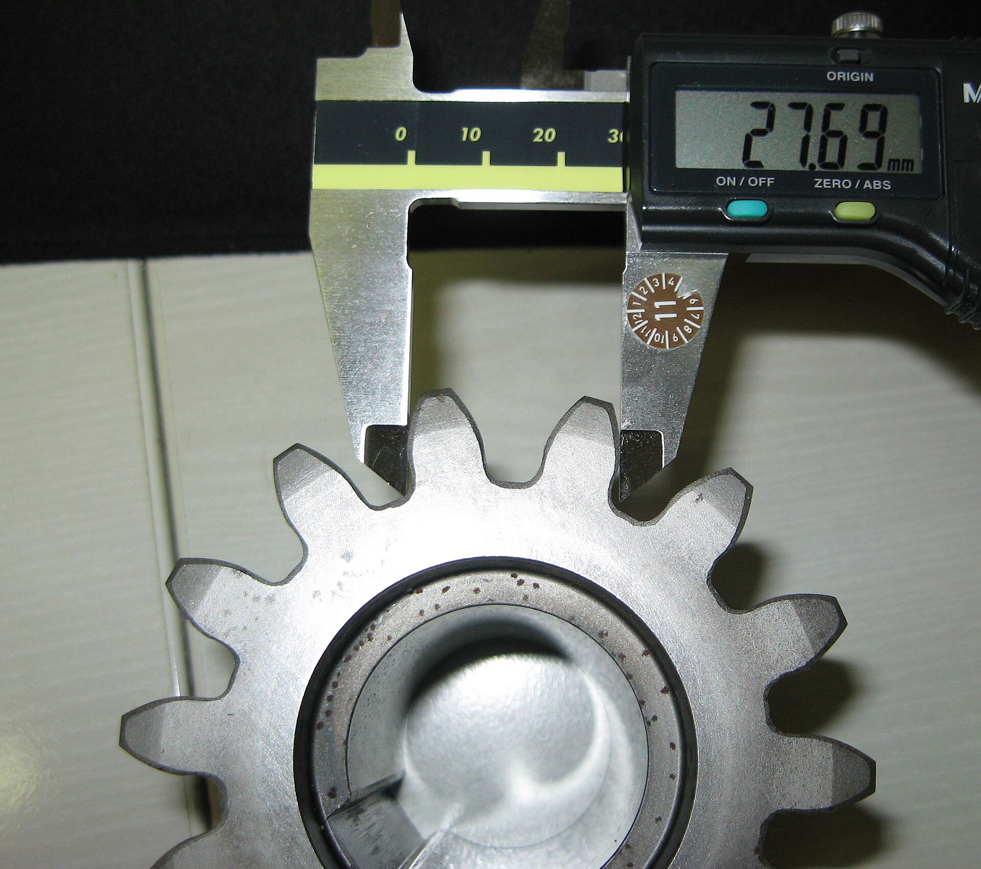
These important parameters must be determined in addition to other gear dimensions (the others can be easily measured with a sliding calliper gauge) in order to provide the configurator with the data it needs.
Tip: the igus 3D printing service works with a precision of ± 0.1mm. A drill hole with a nominal diameter of 10mm, for example, could have a diameter of 10.1mm, but it could also be 9.9mm. So if the gear is to engage easily and turn, it might be expedient to indicate the drill hole in the configurator as having a diameter of 10.05 or 10.1mm. Alternatively, the igus 3D printing service can perform rework and hole reaming. (Please provide this information with the order.)
Determining gear parameters
Specifying the gear module
The most important figure for straight-geared spur gears is the gear module (m), which is indicated in millimetres. The module describes the gear pitch “adjusted” by π. Gears with the same module can be used together. The outside pitch circle diameter (d) can be calculated from the module (m) and the tooth number (n): d = m*n. This is the gear’s effective radius – the outside pitch circles of the gear pairing in question touch tangentially and serve as the basis for calculating the gearbox’s output.
Since most of a gear’s parameters can be calculated based on the module, it is very helpful to know the module. Unfortunately, the outside pitch circle diameter and the module cannot be determined directly with a sliding calliper gauge.

The outside pitch circle diameter can be approximated by inserting two dowel pins at opposite points in the gear teeth and using a sliding calliper gauge to measure the distance between the two pins. One pin diameter is to be subtracted from this value. But this value is correct only if pins with diameters that are correct for the module are used (and the module is what is to be determined, so we don’t know what it is). This technique becomes difficult if there is an uneven number of teeth, since the pins can then not be inserted directly across from one another.

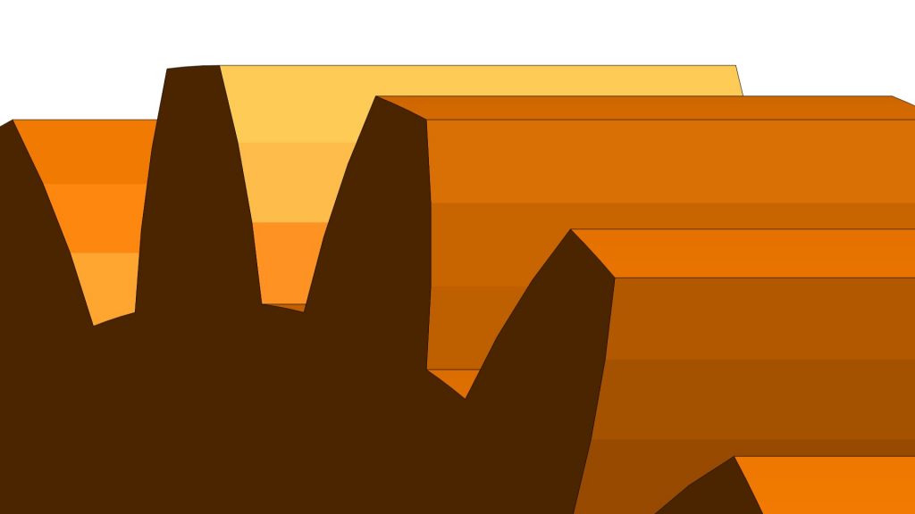
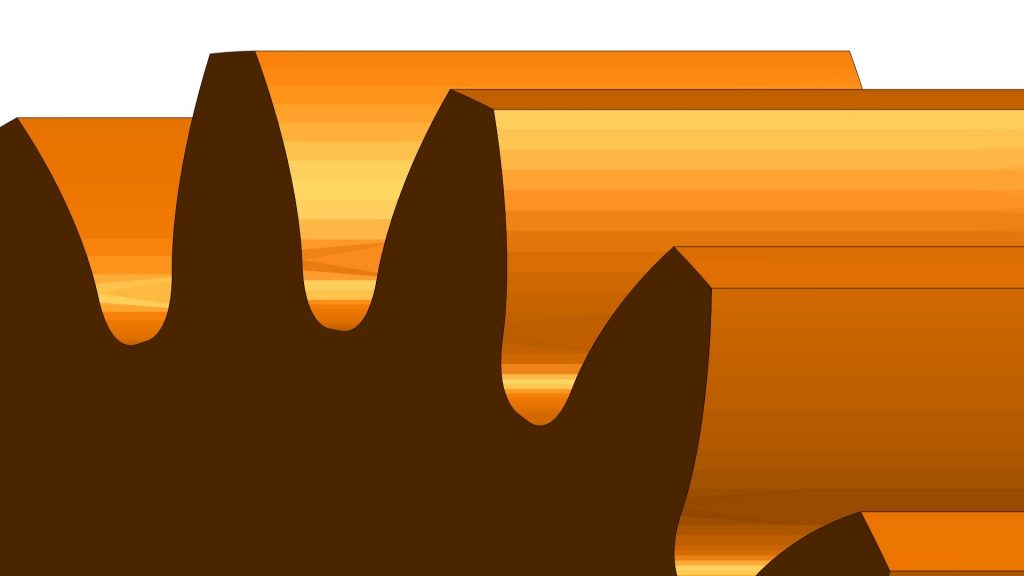
Another option for determining the gear module is calculation based on the base tangent length measurement. To use this method, measure the length twice, as shown in the figure, across different numbers of teeth. It is important that each measurement is in the area of the tooth flanks (involutes), not on the edges of the tooth tips or the tooth root. The gear module can then be measured as follows: m = ( 1− 2)/( ∗ ∗( 1− 2)). 1 and 2 are tooth numbers across which the length was measured, and 1 and 2 are the associated lengths. is the pressure angle (a tooth design parameter – normally 20°).
It is helpful to know that the module in the preferred rows is standardised (DIN 780). Machine-manufactured gears are usually designed according to the values found there. This means that it is a good sign if the value determined shows up in the table – and vice versa.
Specifying the gear module based on the tip diameter
Measuring the tip diameter is easier, and may get you to your goal faster. The tip diameter is the gear’s outer diameter. The gear configurator uses the tooth number and tip diameter to calculate the gear module.
When the other gear dimensions are entered, the configurator has everything it needs.
Note: the configurator may calculate a gear module number that is not in the preferred row. While the gear can be 3D printed without any problem and would probably function in the application, it is a good idea to take a look at the reasons for the discrepancy.
Such an incident is often due to imprecise measurements. If, for instance, the tip diameter is used to calculate a value of m = 1.96, the gear in question probably has a module of 2mm.
Moreover, in individual cases, a profile shift can be applied to the tooth geometry. At the moment, however, the gear configurator cannot take such a shift into account. This can also cause slight deviations in the module calculation and thus in the tooth size.
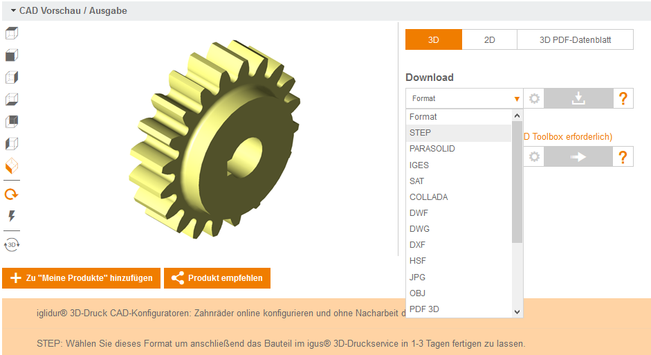
Download a 3D model
At this point, the configured 3D model can be downloaded free-of-charge for further use and without registration. STEP format is needed for queries and component orders from the igus 3D printing service. You can also use it if you want to use the model for more adjustments in your CAD system.
You can also download a model in STL format if you want to print the gear on your own 3D printer, for instance.
Selecting a material and ordering the gear
The iglidur I3 sintering material is good for spur gears – our service life tests showed it lasting longer than milled or injection-moulded gears made of POM.
How can this performance be explained? Unlike many standard gear materials and 3D printing materials, the iglidur 3D printing material contains solid lubricants that increase both its wear-resistance and its resilience. Given relative movement between two gears in which the individual teeth roll past each other under great pressure, this tooth strength is an advantage, reducing coefficient of friction and tooth wear. Incidentally, worm gears are an exception to this rule, since their tooth flanks’ movement with relation to each other is a sliding movement. For this gear type, the iglidur I6 laser sintering material is the better choice.
The STEP model that has just been created can be uploaded to our 3D printing service in the next step and the right material selected; a statement concerning price and delivery time will be generated immediately. Here, you can order directly or send a query. In two to three business days, you will receive your individual, ready-to-install gear and can resume work.
Calculating the service life
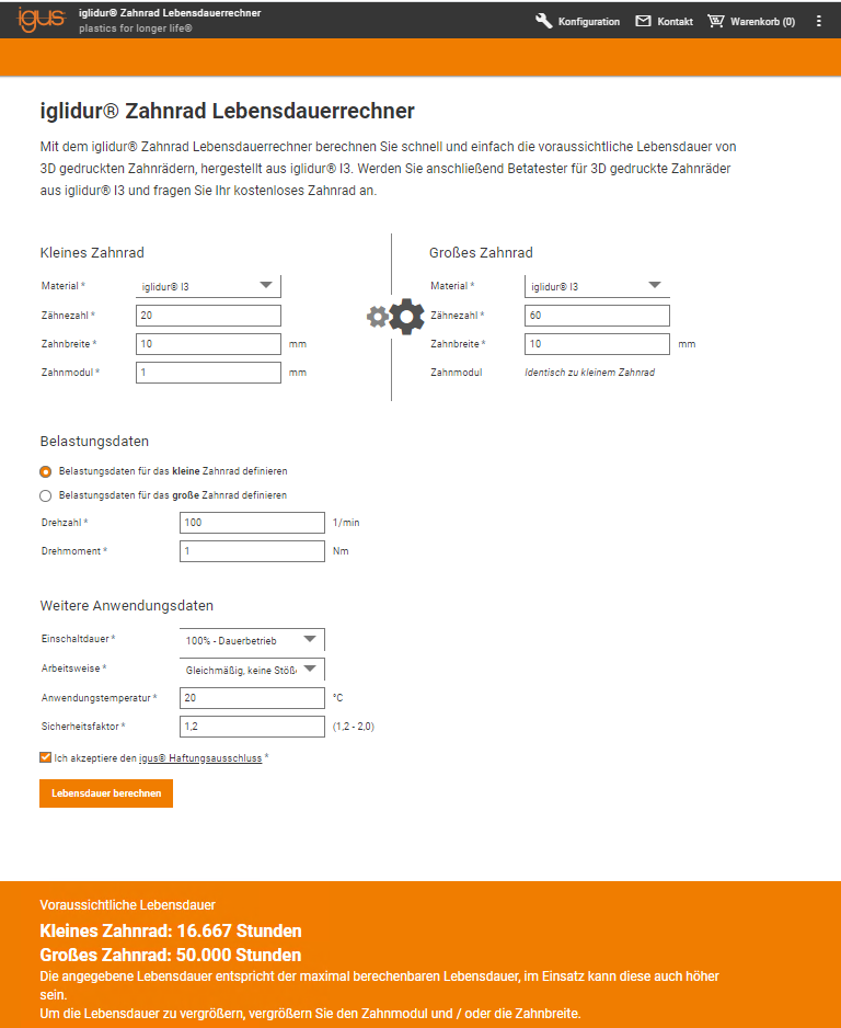
If you want to ensure that the gear you have configured will be able to handle the existing or planned application, you can consult the gear service life calculator: enter the application parameters and receive reliable information about the anticipated gear service life. The service life calculator uses the data from many millions of test cycles in the igus test laboratory as the basis for its prediction.